


|
Environmental Temperature |
-30°C~+75°C |
Relative Humidity |
Not greater than 85% |
|
Working voltage |
AC 220V |
Contact Capacity |
24~380V AC/DC current: 1:5A |
|
Action Itinerary |
|
Extreme Itinerary |
|
|
Action |
|
reliability |
greater than 106 |
|
Protection level |
IP65 |
Reference Weight |
|
Working power: 220VAC ± 15%
Load current: ≤5A
Insulation resistance: >500MΩ
Output signal: switching signal
Ambient temperature: -20 ° C ~ 60 ° C
Ambient humidity: ≤90%
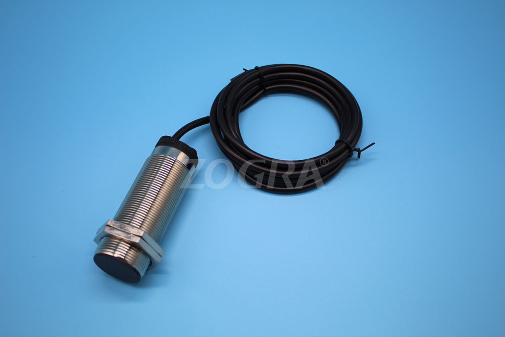
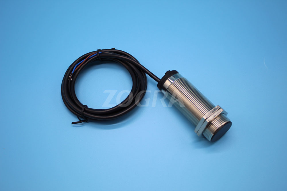
Dimensions: Φ38×105mm
Weight: 0.5KG
Protection level: IP66
Detection speed range: 1-220 rev / min
Trip time: 3-18 seconds
Response time: <2mS
Detection interval H2: ≤ 8mm
Minimum safe working distance H1: ≥20mm
working principle:
The main difference between the slip switch and the proximity switch is that the delay circuit is installed inside. The internal delay can be adjusted according to the different speeds of the passive shaft to achieve the jamming of the protection device. The rotary detector is mounted on the passive shaft as shown in the figure. Through the detection piece mounted on the driven shaft, the speed switching pulse signal is used by the principle of electromagnetic induction (when the detecting piece is rotated to a distance of 4-8 mm from the speed switch), taking FIG. 1 as an example: the instantaneous speed of energization The switch delays the relay to a set number of seconds through a series of relays. The device needs to give the speed switch two pulses when the passive axis of the device rotates. If the speed switch is set to 8 seconds, the device rotates for less than 8 seconds. The speed switch has no action through the series relay (the relay keeps sucking). When the device rotates for more than 8 seconds, the speed switch considers that the jam has been blocked, and the relay is tripped through the series relay (the relay is powered off). ), protection equipment
Features:
1. Non-contact, no moving parts, no wear, long safety life, low maintenance cost, suitable for the environment with harsh environment.
2. Integrated structure, free of setup, debugging, and easy to install.
3. Small size, light weight and long life
4. With load short-circuit protection function - mistakenly connecting the rotating detector directly to the power supply will not damage the rotating detector. (Cannot exceed 1 minute) 5. The output signal can be used in conjunction with field devices or DCS control system.
6. With status indicator. When the device is running normally, the indicator light is “flashing”; when it is stopped, the indicator light is “always on”.
7. Jump time adjustable 3-18S
Installation Notes:
All transmissions, such as screw conveyors, hoists, belt conveyors, zippers, crushers, etc., should be installed at their drive shafts (end of the machine), see figure below. Note: The installation position of the rotation speed monitor in the installation diagram depends on the specific situation. It is not necessary to stick to this picture. As long as the normal operation is not affected, the condition of “pulse signal with uniform probe interval per unit time” can be satisfied. .
Mechanical installation process:
1. Remove the end cap, drill ≥Φ12 hole in the center of the end cap, drill Φ5.l hole in the lower end of the end cover, tap the M6 (cooperate with the two holes of the rotation speed monitor bracket), and fix the end cap and bracket with screws.
2. Drill Φ5.1 hole on the shaft head, tapping M6, deep 10~15mm
3, tighten the double-headed screw
4, install the end cover
5, installed test piece, F ≥ 20mm and fixed with a nut
6, install the rotation speed monitor, adjust G = 4mm
Some machines have long drive shafts and extend beyond the end caps. For this type of situation, it is only necessary to make the test piece into a dove shape and fix it on the shaft head (please note the plane of the test piece and the probe plane of the rotational speed monitor). Keep parallel. If it is installed on a metal base, please pay attention to the distance of F to prevent the equipment from starting up in order to prevent strong magnetic interference.
Electrical wiring: This product is used in series with the intermediate relay (see the electrical wiring diagram above). The intermediate relay coil has a withstand voltage of 220V.
Test piece: the material is ordinary iron sheet, the number of blades is 2 leaves, and the size of the test piece is 100×10×2 mm.
Jump time reference formula: T (trip time) > [60 seconds × 3 (constant value)] ÷ [number of detection × number of revolutions driven]
Precautions:
1. If it is installed on a metal base, please pay special attention to the distance to prevent the device from starting due to strong magnetic interference.
2, the installation distance is best around 4mm, to prevent external changes caused by G changes.
3. The intermediate relay and ZG-SD-IV speed switch are connected in series. The two normally open contacts of the intermediate relay are connected in parallel to increase the current capacity.
4. When the auxiliary rotating shaft is slow, the jumping time can be adjusted.
5. It is strictly forbidden to connect the power directly to the unconnected relay. If the product is damaged due to direct serial connection, it is “man-made damage” and is not covered by the free warranty.
6. Open the ZG-SD-IV speed switch for outdoor installation. Install the rain cover as much as possible to extend the service life of this product.


